An Arduino output cannot power a DC motor directly. An ATmega328P pin is intended for small logic currents, while even a modest motor can draw hundreds of milliamperes and a much larger current when it starts or stalls. A TIP120 NPN Darlington transistor can bridge that gap as a low-side switch: the Arduino supplies a small base current, and the transistor switches the motor current from a separate supply.
The circuit is useful for learning and for moderate DC loads, but the TIP120 is an old, lossy device. Its 5 A and 60 V ratings are absolute device limits, not a promise that a breadboard circuit can switch a 5 A motor safely. For new, efficient designs, a suitable logic-level N-channel MOSFET is usually the better switch.
How the TIP120 Works as a Switch
The three leads of a TIP120 in a TO-220 package are, viewed from the front:
- Base (B): receives current from the Arduino through a resistor.
- Collector (C): connects to the negative side of the motor.
- Emitter (E): connects to the common ground.
The metal tab is electrically connected to the collector, not the base. If several TIP120 devices share a conductive heat sink, their collectors are therefore connected unless each package is electrically insulated from the sink.
A Darlington pair contains two bipolar transistors connected for high current gain. The high gain reduces the base current required from the controller, but it also gives the TIP120 a relatively high collector-emitter saturation voltage. When the switch is on, part of the supply voltage is lost across the transistor rather than applied to the motor.
Parts for the Motor Circuit
- Arduino Uno or another 5 V microcontroller board
- TIP120 NPN Darlington transistor
- DC motor with a known rated voltage, running current, and stall current
- Motor power supply sized for the motor's stall current
- Base resistor, typically a few hundred ohms to 1 kΩ after calculation
- Flyback diode sized for the motor current, such as a 1N4004 for a small, slow-switched motor
- 100 kΩ base-emitter pull-down resistor
- 100 nF ceramic capacitor and a suitable bulk capacitor across the motor supply near the switch
Wiring the Low-Side Switch
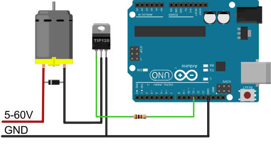
- Connect the motor supply positive terminal to the positive motor terminal.
- Connect the negative motor terminal to the TIP120 collector.
- Connect the TIP120 emitter to the motor supply ground.
- Connect Arduino ground to the same ground. Without this common reference, the base current has no defined return path.
- Connect an Arduino PWM output to the TIP120 base through the calculated base resistor.
- Connect 100 kΩ from base to emitter so the transistor remains off while the Arduino pin is floating during reset.
- Place the flyback diode directly across the motor: cathode, marked by the stripe, to motor positive; anode to the collector side.
In normal operation the diode is reverse-biased. When the transistor turns off, motor inductance tries to keep the current flowing in the same direction. The collector voltage rises until the diode conducts, providing a local path through the motor and diode instead of forcing the TIP120 to absorb the inductive voltage spike.
Choosing the Base Resistor
The TIP120 is controlled by base current. If the Arduino output voltage is \(V_O\), the Darlington base-emitter voltage is \(V_{BE}\), and the resistor is \(R_B\), the approximate base current is
\[ I_B=\frac{V_O-V_{BE}}{R_B}. \]
With \(V_O=5\,\text{V}\), \(V_{BE}\approx2.5\,\text{V}\), and \(R_B=1\,\text{k}\Omega\), the base current is only about \(2.5\,\text{mA}\). That may switch a small motor, but it does not justify assuming that the TIP120 is fully saturated at several amperes. The onsemi TIP120 data sheet specifies saturation test conditions with 12 mA of base current at 3 A collector current and 20 mA at 5 A.
Choose \(R_B\) from the actual load current and the data-sheet switching condition, then verify that the result does not exceed the microcontroller's recommended output current. For example, targeting approximately 10 mA from a 5 V output gives
\[ R_B\approx\frac{5\,\text{V}-2.5\,\text{V}}{10\,\text{mA}}=250\,\Omega. \]
A standard 270 Ω or 330 Ω resistor is a reasonable starting point for testing, provided the controller's pin-current limits are respected. If the required base current is uncomfortable for the microcontroller, do not simply reduce the resistor further; use a proper gate driver, a different transistor stage, or preferably a logic-level MOSFET.
Voltage Drop, Heat, and the 5 A Rating
The transistor's conduction loss is approximately
\[ P_T=V_{CE(\mathrm{sat})}I_C. \]
A Darlington transistor can drop around 2 V under a multi-ampere saturation test condition. At 3 A, that would mean approximately 6 W dissipated in the transistor. The motor would also receive about 2 V less than the supply voltage. This is why a heat sink may be necessary and why the package's thermal resistance, safe operating area, ambient temperature, duty cycle, and motor stall current matter more than the headline 5 A rating.
A solderless breadboard is unsuitable for currents of several amperes. Its contacts and jumper wires add resistance, heat, and unreliable connections. Prototype the logic at low current, then use short, adequately sized conductors and a suitable PCB or terminal wiring for the motor path.
Arduino PWM Example
The following sketch ramps the PWM duty cycle up and down on Uno pin 11. PWM changes the average motor voltage by switching the TIP120 rapidly; it does not make the transistor operate as a linear voltage regulator.
const uint8_t motorPin = 11;

int pwmValue = 0;
int pwmStep = 5;

void setup() {
  pinMode(motorPin, OUTPUT);
  analogWrite(motorPin, 0);
}

void loop() {
  analogWrite(motorPin, pwmValue);
  delay(30);

  pwmValue += pwmStep;

  if (pwmValue >= 255) {
    pwmValue = 255;
    pwmStep = -pwmStep;
  } else if (pwmValue <= 0) {
    pwmValue = 0;
    pwmStep = -pwmStep;
  }
}
A motor may not start at a low duty cycle because starting torque must overcome friction and the initial load. Real control software often applies a short higher-duty start pulse before reducing the command to the desired speed.
Commissioning Checklist
- Measure the motor's stall current or obtain it from the data sheet; do not design from no-load current alone.
- Verify the TIP120 pinout for the exact manufacturer and package before applying power.
- Test the circuit first with a current-limited supply and the motor mechanically unloaded.
- Confirm that the flyback diode is reverse-biased during normal operation.
- Measure the voltage across collector and emitter while the motor runs.
- Calculate \(P_T\) from the measured voltage and current, then check the device temperature.
- Test startup and stall behavior without exceeding the supply, wiring, diode, transistor, or motor ratings.
When to Use a MOSFET or Driver Module Instead
Use a logic-level N-channel MOSFET when efficiency, battery life, low heat, or more than modest current matters. Its conduction loss is approximately \(I^2R_{DS(on)}\), which can be far below the loss caused by the TIP120's saturation voltage. Select it by guaranteed \(R_{DS(on)}\) at the actual Arduino gate voltage, not merely by threshold voltage.
Use an H-bridge motor driver when the motor must reverse, brake actively, or receive controlled current. The TIP120 circuit provides one-direction speed control only. It is intended for low-voltage DC loads and must not be connected directly to mains AC.