PolyEdge is a compact OpenSCAD library for constructing two-dimensional polygons whose corners can be sharp, rounded, or inset independently. It follows the familiar point-list model of OpenSCAD's polygon(), adding one optional corner parameter to each point.
Installation
Download polyedge.scad and place it next to the OpenSCAD design that uses it. Load the module with use when only the module definition is needed, or with include if definitions outside modules should also become visible:
use <polyedge.scad>

polyedge([
    [0, 0],
    [30, 0, 4],
    [30, 20, -3],
    [0, 20]
]);
API
polyedge(points, $fn = $fn); points is an ordered polygon boundary. Every point is either [x, y] or [x, y, corner]. The optional third coordinate controls the corner at that point:
| Corner value | Result |
|---|---|
| corner = 0 or omitted | Keep the original sharp vertex. |
| corner > 0 | Replace the vertex by a circular arc of that radius. |
| corner < 0 | Replace the vertex by a straight inset whose endpoints are -corner units along the adjacent edges. |
The module returns a two-dimensional polygon. Apply linear_extrude(), rotate_extrude(), or another OpenSCAD operation when a three-dimensional solid is required.
Arc Resolution
Rounded corners are sampled according to OpenSCAD's special variable $fn. The number of segments is proportional to the corner's sweep angle, so four 90-degree corners together use approximately $fn segments. If $fn is zero, PolyEdge uses a fallback resolution of 10 segments per full circle.
polyedge(points, $fn = 64); Corner Geometry
Let \(A\), \(B\), and \(C\) be three consecutive polygon vertices, with the corner located at \(B\). Define unit directions from \(B\) toward its neighbors:
\[ \hat{\mathbf a}=\frac{A-B}{\lVert A-B\rVert}, \qquad \hat{\mathbf b}=\frac{C-B}{\lVert C-B\rVert}. \]
If the interior angle is \(\theta\), then \(\hat{\mathbf a}\cdot\hat{\mathbf b}=\cos\theta\). A circular fillet of radius \(r>0\) touches both adjacent edges at the same distance \(d\) from the original vertex. The right triangle formed by a tangent point, the arc center, and \(B\) gives
\[ \boxed{d=r\cot\frac{\theta}{2}}. \]
PolyEdge evaluates the same distance directly from the dot product:
\[ d =r\sqrt{\frac{2}{1-\hat{\mathbf a}\cdot\hat{\mathbf b}}-1}. \]
The arc center lies on the internal angle bisector. Its offset from \(B\) is
\[ \boxed{ \mathbf m =(\hat{\mathbf a}+\hat{\mathbf b}) \frac{r}{\sqrt{1-(\hat{\mathbf a}\cdot\hat{\mathbf b})^2}} }. \]
The tangent points are \(B+d\hat{\mathbf a}\) and \(B+d\hat{\mathbf b}\). PolyEdge samples the circular arc between them, preserving the polygon's winding direction. The underlying fillet construction is developed in rounded corners on a path segment, while the bisector direction follows from normalized vector angle bisectors.
Mixed-Corner Example
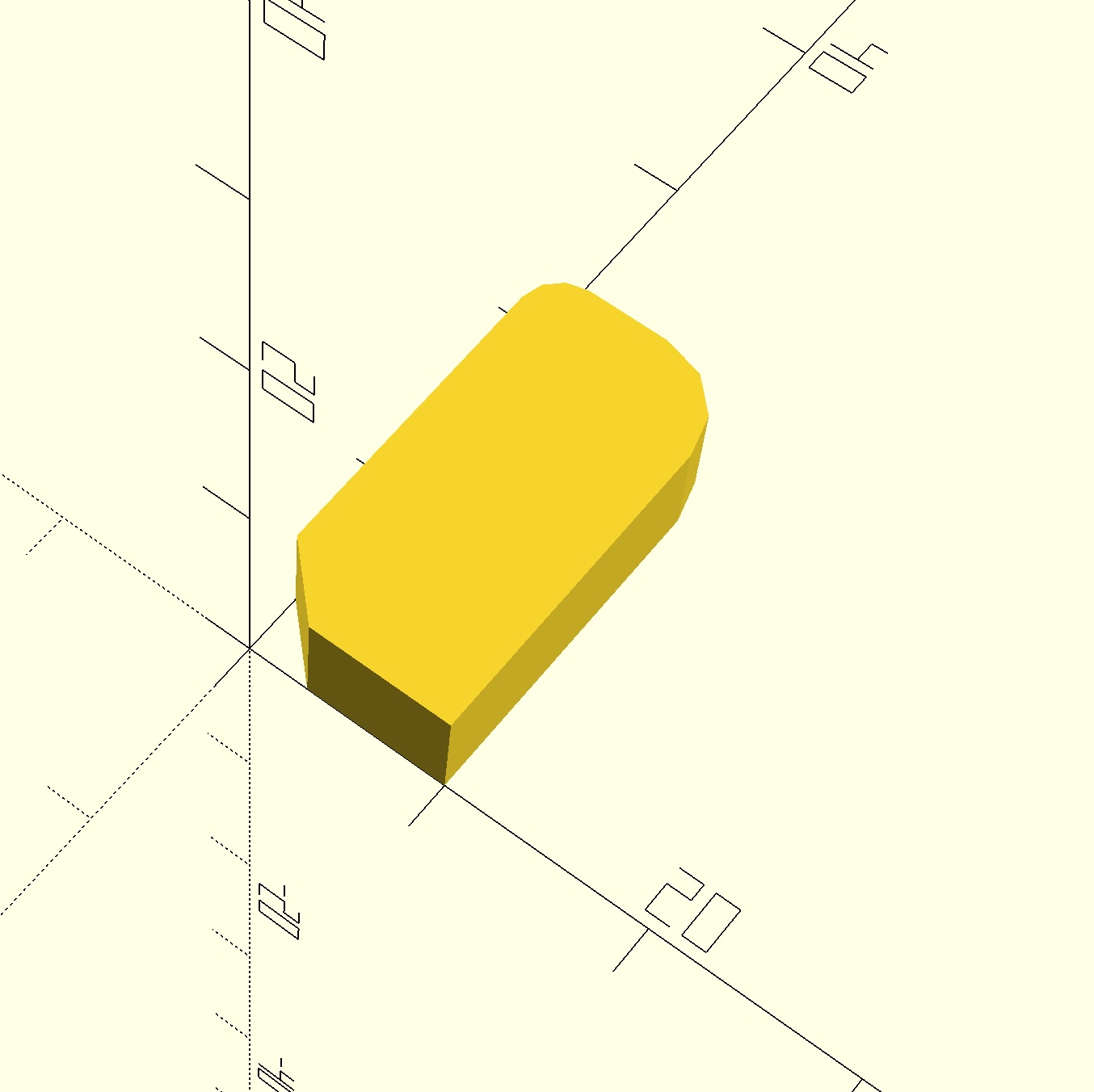
The following profile combines an inset, a sharp corner, and two different fillet radii before extruding the result to a solid:
use <polyedge.scad>

linear_extrude(height = 5)
polyedge([
    [0, 0, -3],
    [10, 0, 0],
    [10, 20, 4],
    [0, 20, 2]
], $fn = 48);
The value \(-3\) cuts the first corner back by three units along each adjacent edge. The positive values create circular corners with radii four and two. The omitted or zero value leaves a sharp vertex.
Center-Finder Example
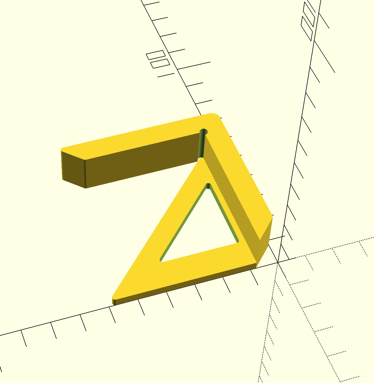
A practical use is a center-finding jig for square stock. Two perpendicular walls register against the workpiece, while the diagonal edge guides a pencil through its center. The design combines three PolyEdge profiles with ordinary OpenSCAD boolean operations.
use <polyedge.scad>

$fn = 20;
width = 60;
height = 15;
edgeRadius = 1;
wallWidth = 8;
notchWallWidth = 10;
notchRadius = 1.5;

difference() {
    union() {
        linear_extrude(height = height)
        polyedge([
            [0, wallWidth, 0],
            [wallWidth, 0, edgeRadius],
            [width, 0, 3],
            [width, width, edgeRadius],
            [width - wallWidth, width - wallWidth, edgeRadius],
            [width - wallWidth, wallWidth, 0]
        ]);

        linear_extrude(height = 3)
        polyedge([
            [0, wallWidth, 0],
            [wallWidth, 0, edgeRadius],
            [width, 0, notchRadius],
            [0, width, edgeRadius]
        ]);
    }

    translate([width - wallWidth, wallWidth, -1])
        cylinder(r = notchRadius, h = height + 2);

    translate([0, 0, -1])
        linear_extrude(height = height)
        polyedge([
            [notchWallWidth, notchWallWidth, edgeRadius],
            [notchWallWidth, width - notchWallWidth * 2, edgeRadius],
            [width - notchWallWidth * 2, notchWallWidth, edgeRadius]
        ]);
}
Valid Input and Limitations
- Provide at least three distinct vertices in boundary order.
- Consecutive vertices must not coincide. PolyEdge reports this as an assertion failure because a zero-length edge has no direction.
- A positive radius must fit on both adjacent edges. If neighboring corner constructions overlap, the generated boundary is not a valid fillet of the original polygon.
- A positive radius at a collinear point leaves that point unchanged because no finite corner arc exists. Backtracking and redundant vertices should still be removed before calling the module.
- Self-intersecting input or independently generated corner segments can still produce a self-intersecting output polygon.
- PolyEdge constructs geometry; it does not automatically solve global radius constraints between neighboring corners.
PolyEdge is distributed as a single MIT-licensed OpenSCAD file and has no runtime dependencies beyond OpenSCAD.