For low-power projects that only need a handful of inputs and outputs, the ATtiny85 is a great choice. This tiny microcontroller still gives you digital pins, analog pins, and PWM outputs, without the size, cost, or power draw of a full Arduino board.
Materials Needed
- Arduino Uno
- ATtiny85 microcontroller
- Breadboard
- Jumper wires
- 10μF capacitor
ATtiny85 Pinout
The most important pins of the ATtiny85 are the analog pins, digital pins, SPI pins and I2C pins.

Step 1: Set Up the Arduino Uno as an ISP
-
Connect the Arduino Uno to your computer using a USB cable.
-
Open the Arduino IDE on your computer.
-
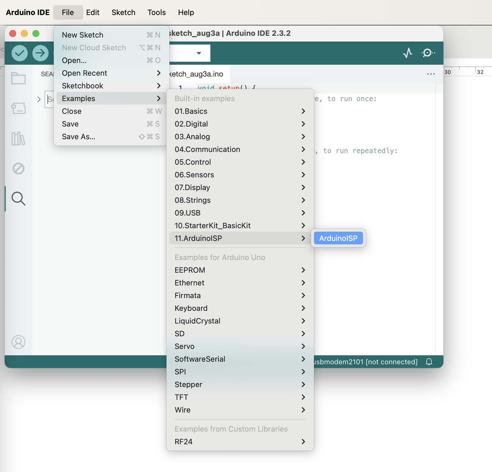
Load the ArduinoISP sketch:
- Go to File > Examples > 11. ArduinoISP > ArduinoISP.
- Upload this sketch to your Arduino Uno.
Step 2: Wire the ATtiny85 to the Arduino Uno
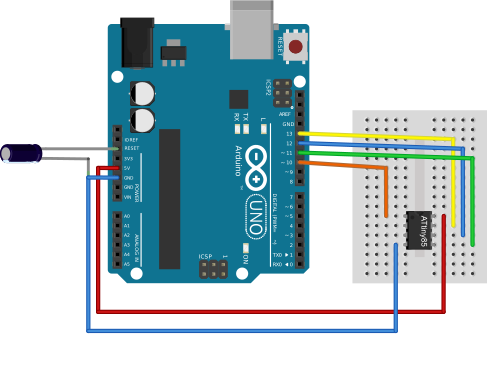
- Disconnect the Arduino Uno from your computer to prevent any power issues during wiring.
- Put the ATtiny85 on the breadboard.
- Connect the Arduino Uno to the ATtiny85 as follows:
- Arduino Uno Pin 10 to ATtiny85 Pin 1 (Reset)
- Arduino Uno Pin 11 to ATtiny85 Pin 5 (MOSI)
- Arduino Uno Pin 12 to ATtiny85 Pin 6 (MISO)
- Arduino Uno Pin 13 to ATtiny85 Pin 7 (SCK)
- Arduino Uno 5V to ATtiny85 Pin 8 (Vcc)
- Arduino Uno GND to ATtiny85 Pin 4 (GND)
- Add a 10μF capacitor between RESET and GND on the Arduino Uno to prevent it from resetting during the upload.
Step 3: Configure the Arduino IDE for ATtiny85
-
Add ATtiny support to the Arduino IDE:
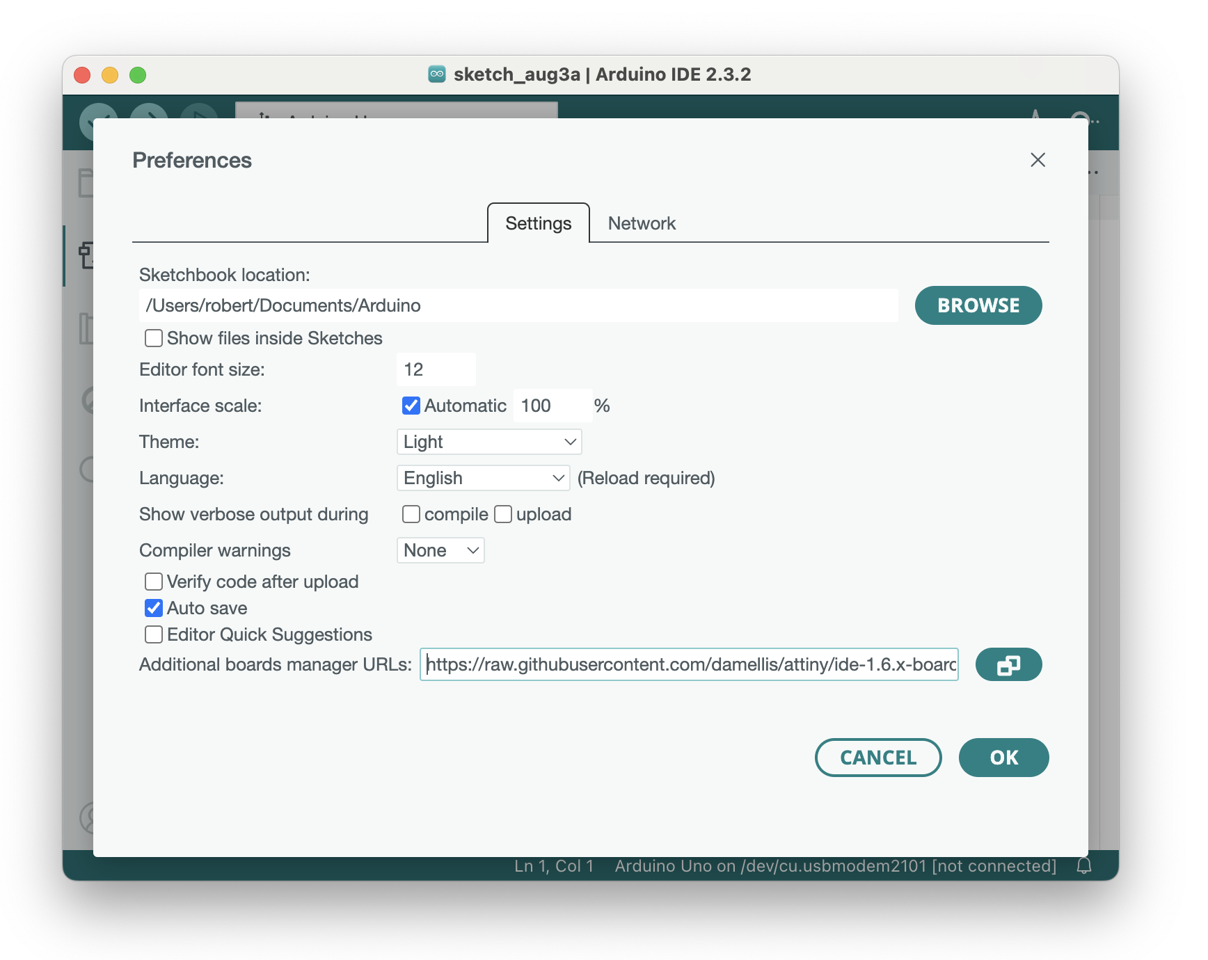
- Go to File > Preferences.
- In the "Additional Boards Manager URLs" field, add this URL: https://raw.githubusercontent.com/damellis/attiny/ide-1.6.x-boards-manager/package_damellis_attiny_index.json
- Put a comma if you have already added other boards, otherwise just paste the URL directly, then click OK.
-
Open the Boards Manager:
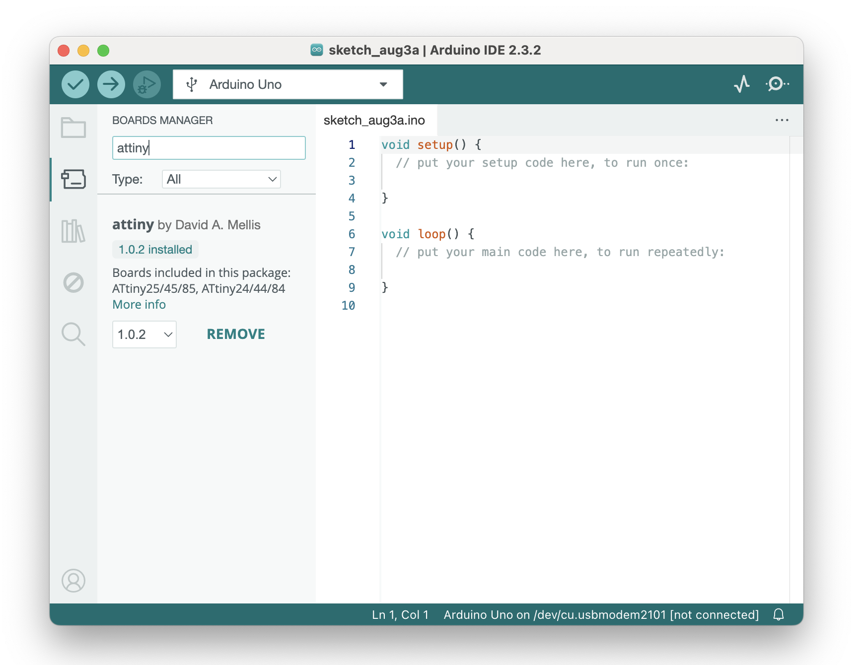
- Go to Tools > Board > Boards Manager.
- Search for "attiny" and install "Attiny by David A. Mellis".
-
Select the ATtiny85 board:
- Go to Tools > Board and select ATtiny25/45/85.
-
Select the ATtiny85 processor:
- Go to Tools > Processor and select ATtiny85.
-
Select the clock speed:
- Go to Tools > Clock and select Internal 8 MHz.
Step 4: Burn the Bootloader
Burn the bootloader to configure the ATtiny85 fuses:
- Go to Tools > Programmer and select Arduino as ISP.
- Go to Tools > Burn Bootloader.
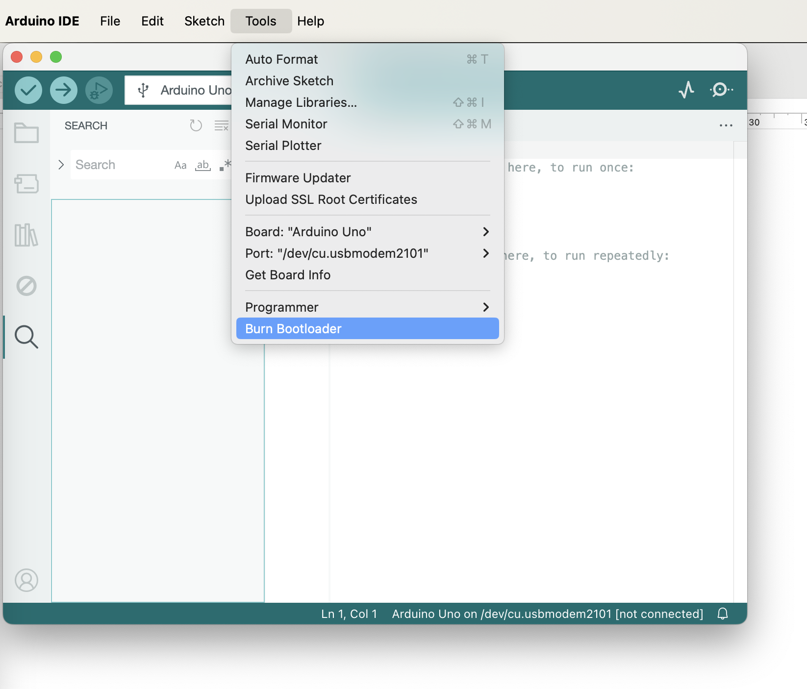
During the bootloader burning process, you will see the LEDs on the Arduino Uno flashing. This takes a few seconds. Once the bootloader has been burned successfully, the LEDs stop flashing and a confirmation message appears in the Arduino IDE.
Step 5: Upload Your Sketch to the ATtiny85
- Write your sketch as you would for any other Arduino board.
- Select the correct programmer:
- Go to Tools > Programmer and make sure Arduino as ISP is selected.
- Upload your sketch using the Sketch > Upload Using Programmer option.
Example Blink Sketch
To operate the ATtiny85, connect VCC and GND as the minimum requirements. For a basic LED blink program, use digital pin 0 to control the LED, and include a 47-ohm resistor in series with the LED to limit the current at 3V. The operating voltage range for the ATtiny85 is 2.7V to 5.5V.
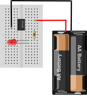
The following sketch blinks an LED on digital pin 0 once per second. Upload it to the ATtiny85 using the Upload Using Programmer option described above.
void setup() {
  pinMode(0, OUTPUT); // Use pin 0 (physical pin 5 on ATtiny85)
}

void loop() {
  digitalWrite(0, HIGH); // Turn the LED on
  delay(1000); // Wait for a second
  digitalWrite(0, LOW); // Turn the LED off
  delay(1000); // Wait for a second
}