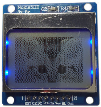
The small LCD sold as a "Nokia 5110 display" is an inexpensive way to add a readable monochrome screen to a microcontroller. Its PCD8544 controller drives an 84 × 48 pixel matrix and accepts commands and display data through a write-only serial interface. The display needs only 504 bytes for a complete framebuffer, which makes it practical even on an Arduino Uno.
Before Connecting the Display
The PCD8544 is a 3.3 V device. Its supply range is 2.7 V to 3.3 V, and its digital inputs are not specified as 5 V tolerant. A 5 V Arduino Uno therefore needs a proper high-to-low level shifter on every signal sent to the display. Powering the LCD itself from 3.3 V does not make direct 5 V GPIO signals safe.
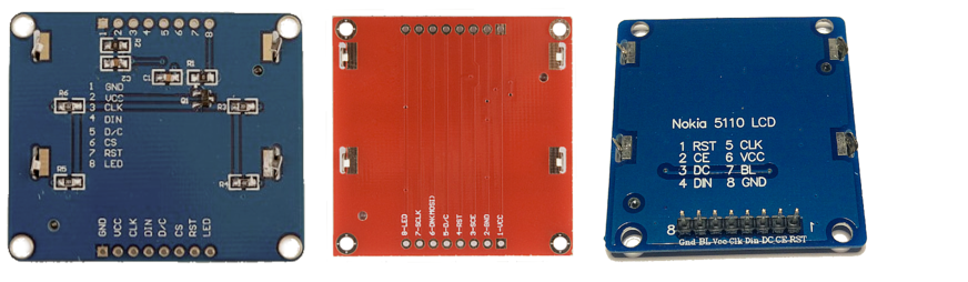
Breakout boards are less consistent than the controller. Pin order, backlight polarity, LED resistor population, and even labels vary between manufacturers. Some boards say "3V-5V" because their backlight includes a resistor; that marking does not change the PCD8544 logic limits. Always wire by printed label and inspect the particular module rather than copying the physical pin order from another board.
PCD8544 Pinout
| Label | Alternative labels | Function |
|---|---|---|
| RST | RESET | Active-low reset. Pull low to reset, then release high. |
| SCE | CE, CS | Active-low chip enable. |
| D/C | DC | Command/data selection: low for a command, high for display data. |
| DIN | DN, MOSI | Serial data input, most-significant bit first. |
| SCLK | CLK | Serial clock input. |
| VCC | VDD | 2.7 V to 3.3 V controller supply. |
| BL | LIGHT, LED | Module-specific LED backlight connection. |
| GND | VSS | Common ground. |
The interface resembles SPI mode 0, but there is no data output from the controller. SCE frames each transfer, D/C selects the interpretation of the next byte, DIN carries the bits, and the controller samples them on the rising edge of SCLK.
Wiring a 3.3 V Microcontroller
A microcontroller whose GPIO also operates at 3.3 V can drive the five control signals directly. Connect VCC to 3.3 V, join the grounds, and use any five digital outputs when the library performs software serial transfers. For hardware SPI, connect DIN to MOSI and SCLK to the board's SCK pin.
Wiring an Arduino Uno
The Uno uses 5 V GPIO, so place a 74HC4050 between the Arduino and the display. Power the 74HC4050 from 3.3 V; its inputs tolerate signals above its supply and its outputs then produce suitable 3.3 V logic. Do not substitute a 74HCT4050 powered at 3.3 V: the HCT family is not specified for that supply voltage.
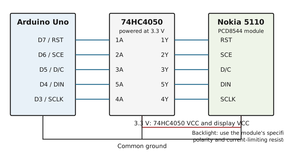
| Arduino Uno | 74HC4050 input → output | Display |
|---|---|---|
| D7 | 1A → 1Y | RST |
| D6 | 2A → 2Y | SCE |
| D5 | 3A → 3Y | D/C |
| D4 | 5A → 5Y | DIN |
| D3 | 4A → 4Y | SCLK |
| 3.3 V | VCC | VCC |
| GND | GND | GND |
Check the pin numbers in the datasheet for the exact 74HC4050 package you bought. Inline resistors alone are not a defined logic-level converter: they limit clamp current and slow edges, but they do not establish a guaranteed 3.3 V high level. A proper buffer is the robust choice.
Backlight
The backlight belongs to the breakout board, not to the PCD8544 controller. Some modules include current-limiting resistors and some do not; polarity also varies. If no resistor is fitted, choose one from the LED forward voltage and the desired current using R = (3.3 V - Vf) / I. Start with a conservative current and confirm the board's schematic or measure it. Do not assume that every module contains four 20 mA LEDs.
Display Memory
The 48 rows are divided into six banks of eight vertical pixels. Each byte controls one vertical group of eight pixels at one of the 84 horizontal positions, so a complete image occupies:
84 columns * 6 banks = 504 bytes Graphics libraries normally draw into this RAM buffer first. A separate update operation transfers all 504 bytes to the controller. Nothing changes on the LCD until that transfer occurs.
Using the Adafruit Libraries
For a new Arduino project, install Adafruit PCD8544 and its Adafruit GFX dependency through the Arduino Library Manager. The constructor below follows the Uno wiring shown above. Its argument order is SCLK, DIN, D/C, SCE, RST.
#include <Adafruit_GFX.h>
#include <Adafruit_PCD8544.h>

Adafruit_PCD8544 display(3, 4, 5, 6, 7);

void setup() {
  display.begin();
  display.setContrast(60);
  display.clearDisplay();

  display.setTextSize(1);
  display.setTextColor(BLACK);
  display.setCursor(6, 20);
  display.println(F("Hello world"));

  display.drawRect(0, 0, 84, 48, BLACK);
  display.display();
}

void loop() {
}
If the screen is blank but the backlight is on, vary the contrast gradually rather than assuming the wiring is correct. The backlight is electrically independent of the LCD. Typical useful contrast values differ between glass and breakout variants.
Drawing a Bitmap
The LCD image generator converts an 84 × 48 monochrome image into a byte array. Store the array in program memory, draw it into the framebuffer, and then transfer the buffer:
const uint8_t image[] PROGMEM = {
  /* 504 generated bytes */
};

display.clearDisplay();
display.drawBitmap(0, 0, image, 84, 48, BLACK);
display.display();
The Original PCD8544 Driver
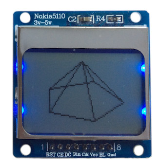
The photographs and early examples for this project used the compact infusion/PCD8544 driver. It exposes the framebuffer directly and provides pixels, lines, rectangles, circles, text, inversion, contrast, bias, and temperature-coefficient control. Its five-argument software-serial constructor uses the order RST, SCE, D/C, DIN, SCLK:
#include <PCD8544.h>

PCD8544 display(7, 6, 5, 4, 3);

void setup() {
  display.init(60);
}

void loop() {
  display.clearBuffer();
  display.strokeRect(3, 3, 78, 42);
  display.strokeLine(3, 45, 42, 3);
  display.strokeLine(42, 3, 80, 45);
  display.update();
  delay(1000);
} 
The original driver is useful when its small API matches an AVR or supported board, while the Adafruit libraries are the more portable default for a current project. The two libraries use different constructor orders and method names, so examples cannot be mixed line by line.
Adding Four Controls for a Game
A simple Snake game needs four direction buttons. A resistor ladder lets the Uno distinguish them with one analog input: each button connects 5 V through a different resistor, while a 4.7 kΩ resistor pulls A0 to ground. The resulting voltage-divider output maps each button to a different ADC range.
With the Uno's default 5 V ADC reference, the nominal readings are approximately 57, 108, 195, and 327. Place decision thresholds between those values rather than directly on them, then calibrate with the actual resistor tolerances and supply voltage:
enum Button : uint8_t {
  BUTTON_NONE,
  BUTTON_80K,
  BUTTON_40K,
  BUTTON_20K,
  BUTTON_10K
};

Button readButton() {
  const int value = analogRead(A0);

  if (value < 29) return BUTTON_NONE;
  if (value < 83) return BUTTON_80K;
  if (value < 152) return BUTTON_40K;
  if (value < 261) return BUTTON_20K;
  return BUTTON_10K;
}
This compact circuit recognizes one button at a time. Simultaneous presses create additional parallel resistance values and should either be ignored in software or handled with separate digital inputs.
Troubleshooting
- No pixels: verify 3.3 V at VCC, common ground, RST release, and the constructor's pin order.
- Backlight only: the LED circuit working says nothing about PCD8544 communication.
- Very faint or dark image: adjust contrast in small steps and check the supply voltage.
- Random columns: shorten breadboard wires, verify SCE and D/C, and reduce serial clock speed.
- Hot display or level shifter: disconnect power immediately and recheck VCC, GND, and pin labels.
References
- [PCD8544]NXP Semiconductors, PCD8544: 48 × 84 pixels matrix LCD controller/driver, Rev. 6, 2010.
- [HC4050]Texas Instruments, CD74HC4050 High-Voltage Logic Level Shifter, product data and datasheet.
- [UNO]Arduino, Arduino Uno Rev3 documentation.