We've all grown up with gamepads in the hands, which makes them ideal to combine them with literally any possible application. A great invention of Nintendo is the Nunchuk, a cheap extension for the Wii U remote. As it uses I2C as transportation protocol, it's easy to access the raw data of the controller. As it is so easy, I thought there must be a standard solution for it, but couldn't find a stable implementation, but only loads of code snippets. That's why I focused on filling this gap and here it is. In this article, I'll guide you through the details and implement it for an Arduino.
Hardware
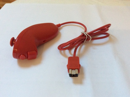
The Nunchuk has two membrane buttons, called button C and button Z. On top of the device is an analog two-axis joystick and the whole device is sensible to movements, since an accelerometer measures forces acting on all three dimensions. It's recommended to operate the Nunchuk with 3v3 and you should defintely use a level shifter if you can't supply that voltage to increase it's lifespan. As a minimum, you'll need the following parts for this set-up:
Parts
- Nintendo Nunchuk (or replica)
- Arduino
- Level Shifter (optional)
- Nunchuk Adapter (optional)
Original Nunchuk or replica
The big question is, should you buy an original Nintendo Nunchuk or a chinese replica. In order to test my Nunchuk driver, I bought both - the original and a cheap copy. Both versions are far away from expensive, but the difference is about 10-15€. What I can say is, the wires of the cable of the original Nunchuk are shielded, which makes them more robust against disturbances. The joystick of the original has a higher quality, it can resolve all movements in the full range of values, while the copy doesn't react to minimal movements. Also the quality of the accelerometer of the original is better. However, I applied a Kalman Filter, which levels these differences. So, if you want a long-living controller, I would go with the original, if you just need a cheap input device, you might have luck with a Nunchuk copy.
Nunchuk connector
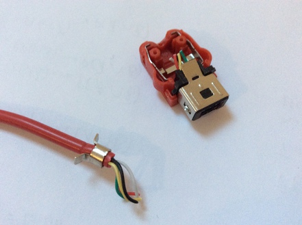
Nintendo connects all peripherals with a proprietary plug. As I don't have a Wii and will not use the controllers for something gaming-related, I ripped apart the connectors. You can get a Nunchuk adapter for a few bucks, if you don't want to do this drastic step, but with some soldering skills, you should be able to repair the plug anyway. I recommend opening the plug, since you can see how the wires are connected to the pins. This is especially important for Nunchuk replicas, since the wires can be connected randomly. Another strange thing is, the original controller has 4 wires and the replica got 5, while the connector actually has 6 pins. Okay, let's go to work and open the connector:
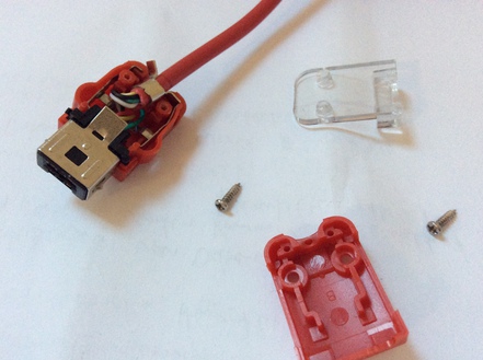
And cut off the wires:
When looking frontal on the plug, you'll see these pins:
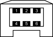
For the original Nunchuk, the following is the color and pin-layout of the connector:
- Green → SDA
- nc
- Red → 3v3
- White → GND
- nc
- Yellow → SCL
For the Nunchuk clone I got, the following is the color and pin-layout of the connector:
- Yellow → SDA
- Black → nc
- Green → 3v3
- Red → GND
- nc
- White → SCL
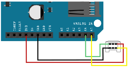
As I said, you should defintely look at how the wires are layed out and not connect anything by it's color. The used acronyms are: nc for not connected, SDA - the data line (must be connected with A4 on the Arduino board) and SCL - the clock (connected with A5). Arduino got a voltage regulator, which allows us to use 3v3 directly. If you want to use the WiiChuck or a similar Nunchuk adapter, connect 3v3 with A2 and GND with A1 - you will later need to call nunchuk_init_power() to initialize these power supply connectors. The following Fritzing sketch illustrates the connection:
Software
I wrote a small header library, which implements the communication with the Nunchuk. In fact, you shouldn't worry about what's going on behind the scenes, it should work just out of the box. If you're interested in the details, I'll explain this in a minute anyway.
The communication with the Nunchuk is made via the TWI bus, which is just another name for I2C (okay, some details are different, which doesn't matter for our purposes however). The speed of the I2C bus is set to Fast Mode (400kHz) by default. In order to use the Nunchuk with your Arduino, only the following is needed:
#include <Wire.h>
#include "nunchuk.h"

void setup() {

    Serial.begin(9600);
    Wire.begin();
    // nunchuk_init_power(); // A1 and A2 is power supply
    nunchuk_init();
}

void loop() {

    if (nunchuk_read()) {
        // Work with nunchuk_data
        nunchuk_print();
    }
    delay(10);
}
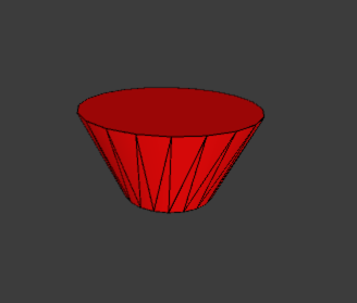
When starting the Processing file shipped with the library, you can balance this cone with your Nunchuk:
Instead of nunchuk_print() a lot of functions can be used to acces the actual data:
Nunchuk Functions
nunchuk_buttonZ():
1 or 0, whether the Z button is pressed or not
nunchuk_buttonC():
1 or 0, whether the C button is pressed or not
nunchuk_joystickX_raw() / nunchuk_joystickX()
nunchuk_joystickY_raw() / nunchuk_joystickY():
The
x- or y-value of the joystick. A raw version for each function gives access to data without calibration.
nunchuk_joystick_angle():
Calculates the angle of the joystick in radians.
nunchuk_accelX_raw() / nunchuk_accelX()
nunchuk_accelY_raw() / nunchuk_accelY()
nunchuk_accelZ_raw() /
nunchuk_accelZ():
The x-, y- or z- value of the accelerometer. A raw version for each function gives
access to data without calibration.
nunchuk_pitch():
Calculates the pitch angle of the controller in radians.
nunchuk_roll():
Calculates the roll angle of the controller in radians.
Note: There is no nunchuk_yaw() function, since an accelerometer can measure only directional forces and no rotational velocity. This circumstance also limits the pitch to just 180° and forces the roll angle to be wrong when the pitch is greater than 180°.
The calculation of the pitch and roll angle also works under a simplifying assumption, that the only velocity acting upon the controller is gravity. This works since the Nunchuk is either held still or experiences a constant velocity from an external force.
Calibration
As described in the function overview, every function of the joystick and the accelerometer comes with a calibrated and a raw version. At the beginning of the library file, some constants define the zero positions. Best thing would be to read the raw measurements of your controller, when you hold it in neutral position and adapt the constants accordingly.
I2C Protocol
The last section here discusses the actual I2C protocol. If you just want to use the controller, this information is not needed, but if you want to understand the protocol, I hope I can save you some time.
I began developing by scanning for the actual address of the Nunchuk with my I2C scanner, which is 0x52. Reading parameters off of the Nunchuk's memory via the I2C bus is quite similar to the communication with a normal I2C EEPROM. Before the data from the Nunchuk can be read, it's necessary to send an initialization sequence.
In order to read data from the Nunchuk, it's necessary to send the address to read from, since the controller of the Nunchuk increments the address with every read. The data we're actually interested in lies at address 0x00 and is 6 bytes long. At address 0x20 and 0x30 (seems to be an exact copy of the bytes at 0x20), 16 bytes of calibration data is stored. At address 0xFA you can find the ident number of the device, which is 0xA4200000 for Nunchuck, 0xA4200101 for Classic Controller, 0xA4200402 for Balance and so on.
When data needs to be written to the Nunchuk the format is analogous to the read command. The first byte is the address, followed by the actual data.
Let's walk through the actual byte sequences of the Nunchuk for the described features:
1. Initialize the Nunchuk:
START, 0x40, 0x00, STOP
This sequence is the normal initialization sequence, which sets the encryption algorithm to default. Every byte which is read from the Nunchuk must then be decrypted with (x ^ 0x17) + 0x17. A better way is disabling encryption with this sequence:
2. Initialize the Nunchuk without encryption:
START, 0xF0, 0x55, STOP
START, 0xFB, 0x00,
STOP
This has the benefit that the actual data can be used without the decryption formula and it will work with Nunchuk-clones as well.
3. Read the device ident from extension register:
START, 0xFA, STOP
READ 6 byte
The data is the ident, which I already mentioned, if the connected device is a Nunchuk or Classic controller and so on.
4. Read measurements from the device:
START, 0x00, STOP
READ 6 byte
What you get in return is described in this overview:
| Bit | ||||||||
|---|---|---|---|---|---|---|---|---|
| Byte | 7 | 6 | 5 | 4 | 3 | 2 | 1 | 0 |
| 1 | Joystick X-Axis [7:0] | |||||||
| 2 | Joystick Y-Axis [7:0] | |||||||
| 3 | Accelerometer X-Axis [9:2] | |||||||
| 4 | Accelerometer Y-Axis [9:2] | |||||||
| 5 | Accelerometer Z-Axis [9:2] | |||||||
| 6 | Az [1:0] | Ay [1:0] | Ax [1:0] | ¬Bc | ¬Bz | |||
So, the button values are inverted, and the LSB bits of the accelerometer are contained in byte 6. In the library, I combine the LSB bits with the rest. I've seen people using the values without the LSB bits, which is a too simplificated way of getting the signal more stable. To me, I prefer a noisy signal from an ADC, which can be easily filtered with a Complementary or a Kalman Filter instead of cutting off the numbers by rounding - where you lose lots of information.
5. Read actual calibration data from the device:
START, 0x20, STOP
READ 16byte
What you get in return is described in this overview:
| Byte | Description |
|---|---|
| 1 | 0G value of X-axis [9:2] |
| 2 | 0G value of Y-axis [9:2] |
| 3 | 0G value of Z-axis [9:2] |
| 4 | LSB of Zero value of X,Y,Z axes |
| 5 | 1G value of X-axis [9:2] |
| 6 | 1G value of Y-axis [9:2] |
| 7 | 1G value of Z-axis [9:2] |
| 8 | LSB of 1G value of X,Y,Z axes |
| 9 | Joystick X-axis maximum |
| 10 | Joystick X-axis minimum |
| 11 | Joystick X-axis center |
| 12 | Joystick Y-axis maximum |
| 13 | Joystick Y-axis minimum |
| 14 | Joystick Y-axis center |
| 15 | Checksum |
| 16 | Checksum |
Byte 0-3 store the zero values of the X, Y and Z axis, whereas bytes 4-7 store the values at 1G (earth gravitation). The calibration data isn't used yet in the software implementation.