A u-blox NEO-6M receiver can add position, UTC time, altitude, speed, and satellite status to an Arduino project through a simple UART connection. The common GY-NEO6MV2 breakout makes the receiver easier to wire, but its power input and its serial logic are not the same electrical interface. Verify both before connecting it to a 5 V Arduino.
Identify the Board Before Wiring It
The NEO-6M module itself is a 3.3 V device. Its data sheet limits the module supply to 3.6 V, and its UART pins are not 5 V tolerant. Many GY-NEO6MV2 breakout boards add a voltage regulator and label their supply input for 3 V to 5 V operation. That regulator protects the supply input only; it does not turn the module's RX pin into a 5 V input.
Use 5 V for VCC only when the exact breakout is documented to accept it and visibly contains the regulator and support components. Do not connect a bare NEO-6M module to 5 V. If the board's identity is uncertain, use a regulated 3.3 V supply sized for receiver startup and acquisition rather than assuming the Arduino Uno's 3.3 V pin can supply every clone safely.
The receiver's 3.3 V TX output is normally recognized as high by the ATmega328P input. In the other direction, the Arduino Uno's 5 V TX output must be level-shifted before it reaches the receiver RX input. A resistor divider is sufficient at the default 9600 baud; a proper logic-level shifter is preferable when several signals or higher data rates are involved.
Parts
- Arduino Uno or compatible 5 V ATmega328P board
- GY-NEO6MV2 breakout with NEO-6M receiver and antenna
- 4.7 kΩ resistor
- 10 kΩ resistor
- Breadboard and jumper wires
Wire the UART
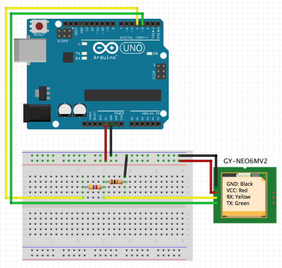
| GPS breakout | Arduino Uno | Purpose |
|---|---|---|
| GND | GND | Common signal reference |
| VCC | 5 V only for a verified 5 V-capable breakout | Board supply |
| TX | D3 directly | GPS output to Arduino software RX |
| RX | D4 through the divider | Optional Arduino output to GPS input |
Serial connections cross: GPS TX goes to the Arduino pin configured as RX. For projects that only consume the receiver's NMEA output, leave GPS RX disconnected. This removes the only 5 V-to-3.3 V signal path and makes the two resistors unnecessary.
If commands must be sent to the receiver, connect D4 through 4.7 kΩ to the divider node, connect 10 kΩ from that node to ground, and connect the node to GPS RX. The ideal output is:
\[V_{out}=5\,\mathrm{V}\frac{10\,\mathrm{k\Omega}}{4.7\,\mathrm{k\Omega}+10\,\mathrm{k\Omega}} \approx 3.40\,\mathrm{V}.\]
Switch off the Arduino before changing wiring. Reversing the divider resistors produces only about 1.6 V and is not the intended circuit.
Check the Raw NMEA Stream First
Most NEO-6M breakouts leave the factory at 9600 baud, 8 data bits, no parity, and one stop bit. Before adding a parser, use the Arduino as a transparent bridge. This separates electrical and baud-rate problems from parsing problems:
#include <SoftwareSerial.h>

constexpr uint8_t GPS_RX_PIN = 3;
constexpr uint8_t GPS_TX_PIN = 4;

SoftwareSerial gpsSerial(GPS_RX_PIN, GPS_TX_PIN);

void setup() {
  Serial.begin(115200);
  gpsSerial.begin(9600);
}

void loop() {
  while (gpsSerial.available() > 0) {
    Serial.write(gpsSerial.read());
  }
}
Upload the sketch and open Serial Monitor at 115200 baud. A functioning connection emits lines resembling $GPGGA, $GPRMC, and $GPGSV. Coordinates may be empty before the first fix; readable sentence names still prove that power, ground, signal direction, and baud rate are working.
SoftwareSerial is adequate for one 9600-baud receiver, but it cannot transmit and receive simultaneously and only one software port can listen at a time. On an Arduino Mega or another board with a spare hardware UART, use Serial1 instead. Hardware serial is more reliable when the sketch also handles timing-sensitive devices or long interrupt-disabled sections.
Parse Fixes with TinyGPSPlus
Install TinyGPSPlus through Arduino IDE's Library Manager. The library consumes the NMEA stream one byte at a time and exposes validity and update state separately. That distinction prevents stale coordinates or an incomplete acquisition sentence from being treated as a new fix.
#include <SoftwareSerial.h>
#include <TinyGPSPlus.h>

constexpr uint8_t GPS_RX_PIN = 3;
constexpr uint8_t GPS_TX_PIN = 4;

SoftwareSerial gpsSerial(GPS_RX_PIN, GPS_TX_PIN);
TinyGPSPlus gps;
bool connectionWarningPrinted = false;

void setup() {
  Serial.begin(115200);
  gpsSerial.begin(9600);
}

void loop() {
  while (gpsSerial.available() > 0) {
    if (gps.encode(gpsSerial.read()) && gps.location.isUpdated()) {
      printFix();
    }
  }

  if (
    !connectionWarningPrinted
    && millis() > 5000
    && gps.charsProcessed() < 10
  ) {
    Serial.println(F("No NMEA data: check power, wiring, and baud rate."));
    connectionWarningPrinted = true;
  }
}

void printFix() {
  if (!gps.location.isValid()) {
    Serial.println(F("NMEA received, but no valid position fix yet."));
    return;
  }

  Serial.print(F("Latitude: "));
  Serial.println(gps.location.lat(), 6);
  Serial.print(F("Longitude: "));
  Serial.println(gps.location.lng(), 6);

  if (gps.satellites.isValid()) {
    Serial.print(F("Satellites: "));
    Serial.println(gps.satellites.value());
  }

  if (gps.hdop.isValid()) {
    Serial.print(F("HDOP: "));
    Serial.println(gps.hdop.hdop(), 1);
  }
}
The loop drains every available byte instead of reading one character per pass. NMEA parsers need complete sentence streams; dropping bytes causes checksum failures and delayed updates. isUpdated() reports a newly decoded location, while isValid() confirms that the receiver marked it usable. Satellite count and HDOP help diagnose reception, but neither replaces the fix-valid flag.
Get the First Position Fix
Place the antenna outdoors with a broad view of the sky and keep it still. A cold receiver may need several minutes to download orbital data and solve its first position. Buildings, coated windows, and indoor testing can attenuate the already weak satellite signals.
Use the failure mode to choose the next check:
| Observation | Likely cause |
|---|---|
| No serial characters | Power, common ground, crossed TX/RX, wrong pin, or wrong baud rate |
| Unreadable characters | Baud-rate mismatch or signal-integrity problem |
| Valid NMEA sentences without coordinates | No satellite fix yet; move outdoors and wait |
| Intermittent checksum failures | Dropped SoftwareSerial bytes, long wiring, electrical noise, or blocked interrupts |
| Fix works until other code runs | The loop is not draining the serial buffer often enough |
Many boards include an LED whose blink pattern changes after acquisition, but parsed fix validity is the reliable application signal. NEO-6 is an older GPS generation; boards sold under similar names may contain different modules or firmware. Trust the exact board marking and observed NMEA output rather than a marketplace title.
Forward NMEA to a Computer
The bridge sketch can also feed a computer over USB. For Node.js projects, the GPS.js NMEA parser accepts arbitrary serial chunks, validates sentence checksums, and maintains a normalized receiver state. This is useful when the Arduino only provides electrical integration and the host performs logging, mapping, or telemetry.
Keep the Arduino USB baud rate at 115200 and the receiver side at 9600. The faster host link prevents the forwarding buffer from becoming the bottleneck. Do not send Serial Monitor text back to the receiver unless GPS RX is connected through a level shifter and the bytes form a command supported by that receiver firmware.
References
- [u-blox]u-blox NEO-6 Data Sheet.
- [Arduino-SoftwareSerial]Arduino Documentation: SoftwareSerial Library.
- [TinyGPSPlus]TinyGPSPlus NMEA Parser.
- [NMEA]NMEA 0183 Standard.