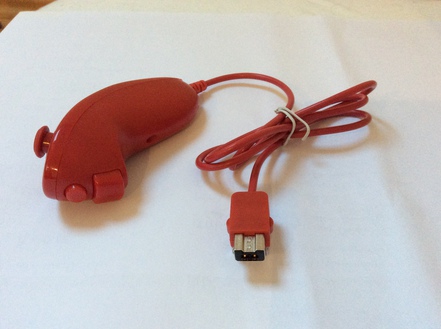
The Nintendo Nunchuk is a compact input device with a two-axis joystick, two buttons, and a three-axis accelerometer. Its extension connector carries power and an I2C-compatible bus, so an Arduino can read the controller without emulating a Wii Remote.
The electrical interface is simple, but reliable operation depends on three details: keep the controller on a 3.3V supply, do not trust clone wire colors, and decode the lower accelerometer bits from the final report byte. The driver and protocol below handle both original controllers and many compatible replicas.
The WebIO Nunchuk driver provides direct browser access with a live joystick, button, acceleration, and tilt visualization.
Hardware and Electrical Limits
The minimum useful setup consists of:
- A Nintendo Nunchuk or compatible controller
- An Arduino or another microcontroller with I2C support
- A Nunchuk breakout adapter or a carefully opened extension connector
- A bidirectional I2C level shifter when the microcontroller uses 5V logic
- Pull-up resistors to 3.3V if they are not already present on the adapter
Power the Nunchuk from 3.3V. On a 5V Arduino Uno, route SDA and SCL through a bidirectional level shifter and keep the controller-side pull-ups at 3.3V. A direct connection can appear to work, but 5V pull-ups place the controller outside its intended electrical conditions. Powering the Nunchuk from GPIO pins is also best avoided: use the board's regulated 3.3V and GND pins instead.
Original Controller and Replicas
The original controller tested here has a shielded cable, a smoother joystick response, and less accelerometer noise than the inexpensive replica. Filtering can reduce noise, but it cannot recover resolution lost to a large joystick dead zone or poor sensor mechanics. For a permanent control interface, the original hardware remains the more predictable choice; replicas are still useful when cost matters more than repeatability.
Nunchuk Connector and Pinout
Nintendo uses a proprietary six-position extension connector. A breakout adapter preserves the plug and is the safest option. If the connector is opened, inspect the conductors before cutting or soldering: clone manufacturers do not follow a dependable wire-color convention.
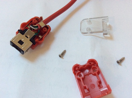
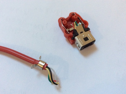
The following view and numbering are used throughout this guide:
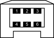
| Pin | Signal | Original unit tested | Replica tested |
|---|---|---|---|
| 1 | SDA | Green | Yellow |
| 2 | Not connected | No wire | Black |
| 3 | 3.3V | Red | Green |
| 4 | GND | White | Red |
| 5 | Not connected | No wire | No wire |
| 6 | SCL | Yellow | White |
These colors describe only the two photographed controllers. Verify continuity from connector to wire before applying power to any other unit.
Wiring an Arduino Uno
| Nunchuk signal | Arduino Uno connection | Note |
|---|---|---|
| 3.3V | 3.3V | Use the regulated supply, not a digital output |
| GND | GND | Ground must be shared with the level shifter |
| SDA | A4 or SDA through a level shifter | Pull up the controller side to 3.3V |
| SCL | A5 or SCL through a level shifter | Pull up the controller side to 3.3V |
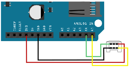
The legacy wiring illustration shows the direct connection used during the original experiment. Add a bidirectional level shifter between the 5V Uno and the 3.3V controller for a robust present-day build. Native 3.3V microcontrollers can connect SDA and SCL directly when their pull-ups also use 3.3V.
Using the Arduino Driver
The original header-only driver and its Processing visualization are preserved in the source repository. The header name is case-sensitive on many systems: include Nunchuk.h, not nunchuk.h.
#include <Wire.h>
#include "Nunchuk.h"

void setup() {
    Serial.begin(9600);
    Wire.begin();

    // The original controller supports I2C Fast Mode.
    // Use 100000 if a replica is unreliable at 400 kHz.
    Wire.setClock(400000UL);

    nunchuk_init();
}

void loop() {
    if (nunchuk_read()) {
        Serial.print(nunchuk_joystickX());
        Serial.print(',');
        Serial.print(nunchuk_joystickY());
        Serial.print(',');
        Serial.print(nunchuk_accelX());
        Serial.print(',');
        Serial.print(nunchuk_accelY());
        Serial.print(',');
        Serial.print(nunchuk_accelZ());
        Serial.print(',');
        Serial.print(nunchuk_buttonZ());
        Serial.print(',');
        Serial.println(nunchuk_buttonC());
    }

    delay(10);
}
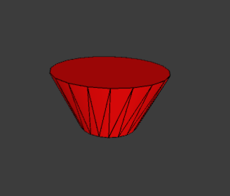
The bundled demo.ino uses nunchuk_print() to produce the same seven-column stream. The Processing sketch consumes that stream and renders the controller's tilt as a balancing cone.
Arduino Driver API
| Function or buffer | Purpose |
|---|---|
nunchuk_init() | Initializes the extension and, by default, disables payload encryption |
nunchuk_read() | Reads one six-byte report and returns nonzero only when all bytes arrived |
nunchuk_buttonZ(), nunchuk_buttonC() | Returns 1 while the corresponding active-low button is pressed |
nunchuk_joystickX_raw(), nunchuk_joystickY_raw() | Returns the unsigned eight-bit joystick samples |
nunchuk_joystickX(), nunchuk_joystickY() | Returns samples relative to the configured center constants |
nunchuk_joystick_angle() | Returns atan2(y, x) in radians |
nunchuk_accelX_raw(), nunchuk_accelY_raw(), nunchuk_accelZ_raw() | Returns the complete unsigned ten-bit acceleration samples |
nunchuk_accelX(), nunchuk_accelY(), nunchuk_accelZ() | Returns samples relative to the configured zero-g constants |
nunchuk_pitch(), nunchuk_roll() | Returns gravity-based tilt estimates in radians |
nunchuk_print() | Prints either CSV data or verbose diagnostics when NUNCHUK_DEBUG is defined |
nunchuk_data[6] | Contains the most recently decoded measurement report |
nunchuk_cali[16] | Reserves storage for the calibration block; the v0.0.1 header does not populate it automatically |
The AVR-only nunchuk_init_power() helper drives two analog-header GPIO pins as power rails. Its polarity depends on adapter orientation and it bypasses the recommendation to use a regulated supply, so it should be treated as a legacy convenience rather than a default setup step.
I2C Address and Complete Register Map
The Nunchuk uses the seven-bit I2C address 0x52. On a logic analyzer this appears as bus byte 0xA4 for writes and 0xA5 for reads because the seven-bit address is shifted left and combined with the read/write bit. Arduino's Wire API always expects 0x52.
| Register | Length or value | Access | Role |
|---|---|---|---|
0x00 | 6 bytes | Read | Joystick, accelerometer, and button report |
0x20 | 16 bytes | Read | Primary calibration block |
0x30 | 16 bytes | Read | Observed mirror of the calibration block on compatible devices |
0x40 | 0x00 | Write | Legacy initialization with encoded report bytes |
0xF0 | 0x55 | Write | First stage of unencrypted extension initialization |
0xFA | 6 bytes | Read | Extension identifier; the source abbreviates a Nunchuk as 0xA4200000 |
0xFB | 0x00 | Write | Second stage of unencrypted extension initialization |
This table includes every register used or documented by the supplied driver and its accompanying protocol notes, including calibration and identification registers that the normal read loop does not consume.
Extension Identifiers
The driver's debug path documents these abbreviated identifiers from the six-byte block at 0xFA:
| Identifier | Extension |
|---|---|
0xA4200000 | Nintendo Nunchuk |
0xA4200101 | Classic Controller |
0xA4200402 | Balance Board |
Read all six bytes and compare the relevant identifier bytes rather than assuming every device at 0x52 uses the Nunchuk report format.
Initialization and Read Transactions
The default driver disables report encryption with two register writes:
START  0x52 write  0xF0  0x55  STOP
START  0x52 write  0xFB  0x00  STOP
A robust report read selects register 0x00 before requesting six bytes:
START  0x52 write  0x00        STOP
START  0x52 read   6 bytes     NACK  STOP
The legacy encrypted path writes 0x00 to register 0x40. Each returned byte must then be decoded with (value ^ 0x17) + 0x17. Disabling encryption avoids that transform and is generally more compatible with replicas.
Some controllers need a short delay between selecting a register and requesting its payload. If the first read is incomplete, begin at 100kHz, add a 1ms delay after the register write, and only then increase the bus speed.
Six-Byte Report Format
| Byte | Bits | Meaning |
|---|---|---|
| 0 | 7:0 | Joystick X |
| 1 | 7:0 | Joystick Y |
| 2 | 7:0 | Accelerometer X bits 9:2 |
| 3 | 7:0 | Accelerometer Y bits 9:2 |
| 4 | 7:0 | Accelerometer Z bits 9:2 |
| 5 | 7:6 | Accelerometer Z bits 1:0 |
| 5:4 | Accelerometer Y bits 1:0 | |
| 3:2 | Accelerometer X bits 1:0 | |
| 1:0 | Active-low C and Z button bits |
The complete ten-bit values and button states are reconstructed as follows:
uint16_t accelX = ((uint16_t) report[2] << 2) | ((report[5] >> 2) & 0x03);
uint16_t accelY = ((uint16_t) report[3] << 2) | ((report[5] >> 4) & 0x03);
uint16_t accelZ = ((uint16_t) report[4] << 2) | ((report[5] >> 6) & 0x03);

bool buttonZ = (report[5] & 0x01) == 0;
bool buttonC = (report[5] & 0x02) == 0;
Dropping the two low bits reduces each accelerometer axis from 10-bit to 8-bit resolution. It may make a noisy signal look calmer, but it discards information rather than filtering it. Preserve all ten bits, then apply a low-pass, complementary, or Kalman filter when the application genuinely needs smoothing.
Calibration Data
The 16-byte block at 0x20 is organized as follows:
| Bytes | Meaning |
|---|---|
| 0-2 | Zero-g X, Y, and Z values, bits 9:2 |
| 3 | Low bits of the three zero-g values |
| 4-6 | One-g X, Y, and Z values, bits 9:2 |
| 7 | Low bits of the three one-g values |
| 8-10 | Joystick X maximum, minimum, and center |
| 11-13 | Joystick Y maximum, minimum, and center |
| 14-15 | Calibration checksum bytes |
The v0.0.1 driver instead subtracts compile-time center constants and leaves nunchuk_cali unused. For a specific controller, record neutral joystick values and stationary accelerometer values first. Reading the device calibration block is useful, but replicas may return different layouts or unreliable data, so validate every field before using it automatically.
Tilt, Motion, and the Missing Yaw Angle
The driver estimates pitch and roll with atan2() ratios of the calibrated acceleration axes. These are gravity-based tilt angles, not a complete orientation solution. They work best while the controller is stationary or moving slowly enough that gravity dominates the measured specific force.
Linear acceleration temporarily tilts the estimated gravity vector. There is also no nunchuk_yaw(): an accelerometer cannot observe rotation around gravity while held level. Stable yaw requires another reference such as a gyroscope integrated over time and corrected by a magnetometer or an external tracking system.
Troubleshooting
| Symptom | Likely cause | Check |
|---|---|---|
No device at 0x52 | Wrong pinout, missing ground, or damaged controller | Verify connector orientation, continuity, 3.3V, and shared ground |
All bytes are 0xFF or unstable | Wrong pull-up voltage or signal-integrity problem | Check the level shifter, 3.3V pull-ups, cable length, and bus speed |
| Only the first read fails | Register pointer or startup timing | Select 0x00, wait 1ms, then request six bytes |
| Buttons appear reversed | Button bits are active-low | Pressed means the corresponding bit is zero |
| Acceleration changes in steps of four | Low accelerometer bits were discarded | Merge byte 5 bits 7:2 into the three axis values |
| Replica works at 100kHz but not 400kHz | Clone timing or signal-integrity limit | Keep the slower clock; report throughput remains ample |
Once the electrical layer and six-byte parser are reliable, the Nunchuk becomes a practical general-purpose input device for robots, camera rigs, motorized mechanisms, and interactive installations.