Design conditions

Choose the electrical limits

Results update immediately. Add the input resistance of an ADC, amplifier, or other load to account for voltage sag.

Selected divider
Load High-Z Vin 5 V R1 R2 Vout
Actual output
Nominal error
Input current
Resistor loss
Output impedance
Tolerance range

Best standard-value pairs

Voltage Divider Calculator

Robert Eisele

A voltage divider uses two resistors to produce a fraction of an input voltage. The calculator above searches real IEC preferred values rather than returning an ideal ratio that may not be available as a component. It also models the load connected to the output, resistor tolerance, current draw, output impedance, and power dissipation.

The Ideal Voltage Divider

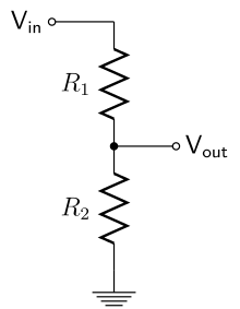
Two resistors are connected in series between the input voltage and ground. With no load attached, the same current flows through both resistors:

\[ I=\frac{V_{\mathrm{in}}}{R_1+R_2}. \]

The output is the voltage across the lower resistor. Ohm's law therefore gives

\[ V_{\mathrm{out}}=IR_2 =V_{\mathrm{in}}\frac{R_2}{R_1+R_2}. \]

Only the ratio between the resistors determines the ideal output voltage. Multiplying both values by the same factor leaves the ratio unchanged, but reduces the current and power consumption.

What Changes When a Load Is Connected

A real circuit draws current from the output. If its input resistance is represented by \(R_L\), it sits in parallel with \(R_2\). The effective lower resistance becomes

\[ R_{\mathrm{lower}}=R_2\parallel R_L =\frac{R_2R_L}{R_2+R_L}, \]

and the loaded output voltage is

\[ V_{\mathrm{out,loaded}} =V_{\mathrm{in}}\frac{R_2\parallel R_L}{R_1+(R_2\parallel R_L)}. \]

A finite load always lowers the effective resistance of the bottom branch. Ignoring it therefore predicts an output voltage that is too high. A common design guideline is to make the divider current at least ten times the load current, but this is only a rule of thumb: the loaded equation gives the actual result.

Choosing Standard Resistor Values

Resistors are sold in preferred-number series. E6 contains six nominal values per decade, E24 contains 24, and E96 contains 96. A denser series can approximate the requested ratio more closely, while the selected resistance range controls the tradeoff between current consumption and output impedance.

The tool evaluates every pair in the selected series and range. Candidates are ordered by nominal voltage error. Pairs with equal error are ordered by lower input power, so equivalent ratios favor larger resistance values.

Tolerance and Worst-Case Output

The nominal ratio is not the whole specification. The lowest output occurs when \(R_1\) is high and \(R_2\) is low; the highest output occurs in the opposite corner. For a fractional tolerance \(t\), these bounds are evaluated as

\[ V_{\min}=V_{\mathrm{out}}\bigl(R_1(1+t),R_2(1-t)\bigr), \qquad V_{\max}=V_{\mathrm{out}}\bigl(R_1(1-t),R_2(1+t)\bigr). \]

The range shown by the calculator is a worst-case resistor-tolerance interval. It does not include input-supply tolerance, temperature coefficient, PCB leakage, ADC sampling current, or resistor self-heating.

Current, Power, and Output Impedance

The resistor losses follow directly from \(P=I^2R\). The upper resistor carries the full source current, while the lower resistor carries only the part that does not flow into the load. Each resistor must have a suitable power rating with practical thermal margin.

Viewed from the output with the ideal voltage source shorted, the divider has a Thevenin resistance

\[ R_{\mathrm{th}}=R_1\parallel R_2. \]

A high Thevenin resistance saves current but makes the output more sensitive to leakage, capacitive charging, and time-varying loads. For an ADC input, also check the manufacturer's maximum source-impedance and acquisition-time requirements.

When Not to Use a Voltage Divider

A divider is appropriate for references, sensing, bias networks, and high-impedance signal inputs. It is not a voltage regulator and should not power a load whose current changes substantially. Use a buffer, regulator, or converter when the output must remain stable under load.

Do not apply a basic low-voltage calculation blindly to mains or other hazardous voltages. Working-voltage ratings, creepage, clearance, surge energy, fault behavior, isolation, and certified component requirements become safety-critical.