For numerous low-power applications that require only a few inputs and outputs, the ATtiny85 is an excellent choice. This versatile microcontroller offers digital pins, analog pins, PWM outputs, and many more, making it well-suited for tasks where an Arduino might be too costly or energy-consuming.
Materials Needed
- Arduino Uno
- ATtiny85 microcontroller
- Breadboard
- Jumper wires
- 10μF capacitor
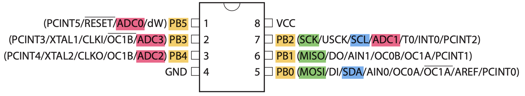
ATTiny85 Pinout
The most important pins of the ATTiny85 are the analog pins, digital pins, SPI pins and I2C pins.
Step 1: Set Up the Arduino Uno as an ISP
Connect the Arduino Uno to your computer using a USB cable.
Open the Arduino IDE on your computer.
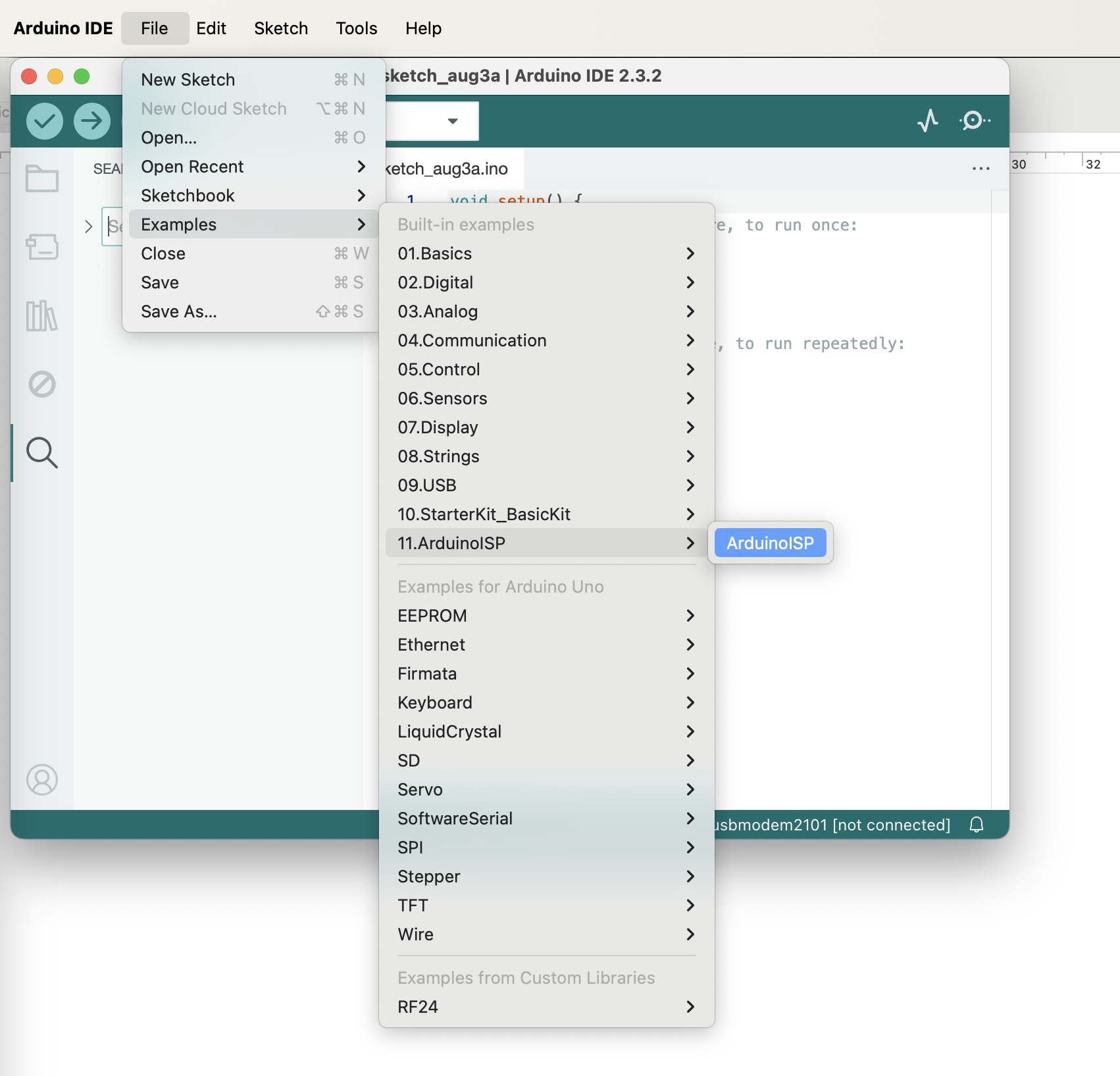
Load the ArduinoISP sketch:
- Go to File > Examples > 11. ArduinoISP > ArduinoISP.
- Upload this sketch to your Arduino Uno.
Step 2: Wire the ATtiny85 to the Arduino Uno

- Disconnect the Arduino Uno from your computer to prevent any power issues during wiring.
- Put the ATtiny85 to the breadboard.
- Connect the Arduino Uno to the ATtiny85 as follows:
- Arduino Uno Pin 10 to ATtiny85 Pin 1 (Reset)
- Arduino Uno Pin 11 to ATtiny85 Pin 5 (MOSI)
- Arduino Uno Pin 12 to ATtiny85 Pin 6 (MISO)
- Arduino Uno Pin 13 to ATtiny85 Pin 7 (SCK)
- Arduino Uno 5V to ATtiny85 Pin 8 (Vcc)
- Arduino Uno GND to ATtiny85 Pin 4 (GND)
- Add a 10μF capacitor between RESET and GND on the Arduino Uno to prevent it from resetting during the upload.
Step 3: Configure the Arduino IDE for ATtiny85
Add ATtiny support to the Arduino IDE:
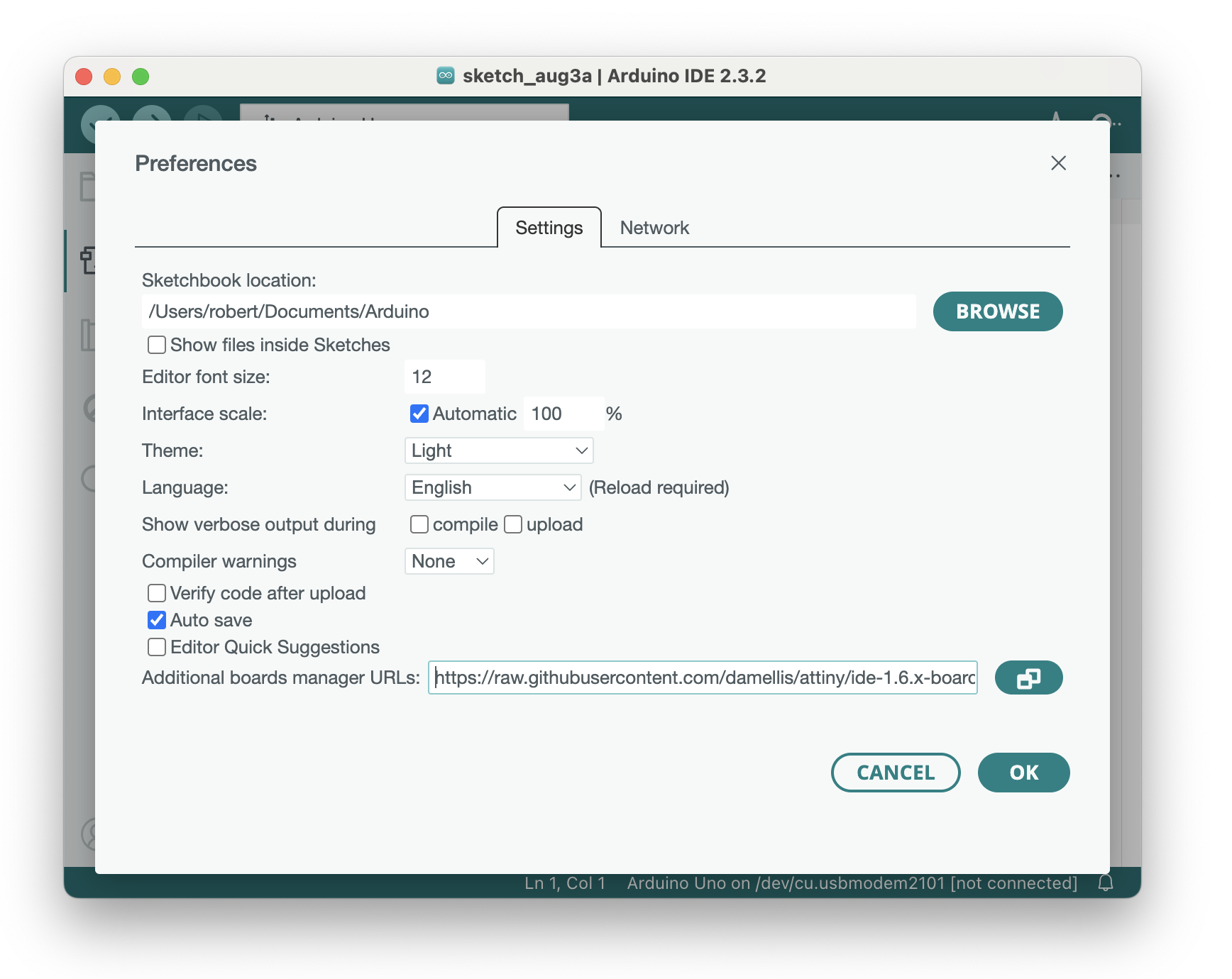
- Go to File > Preferences
- In the "Additional Boards Manager URLs" field, add this URL: https://raw.githubusercontent.com/damellis/attiny/ide-1.6.x-boards-manager/packagedamellisattiny_index.json
- Put a comma if you have added other boards otherwise you can directly paste the board URL link and then click on the OK button.
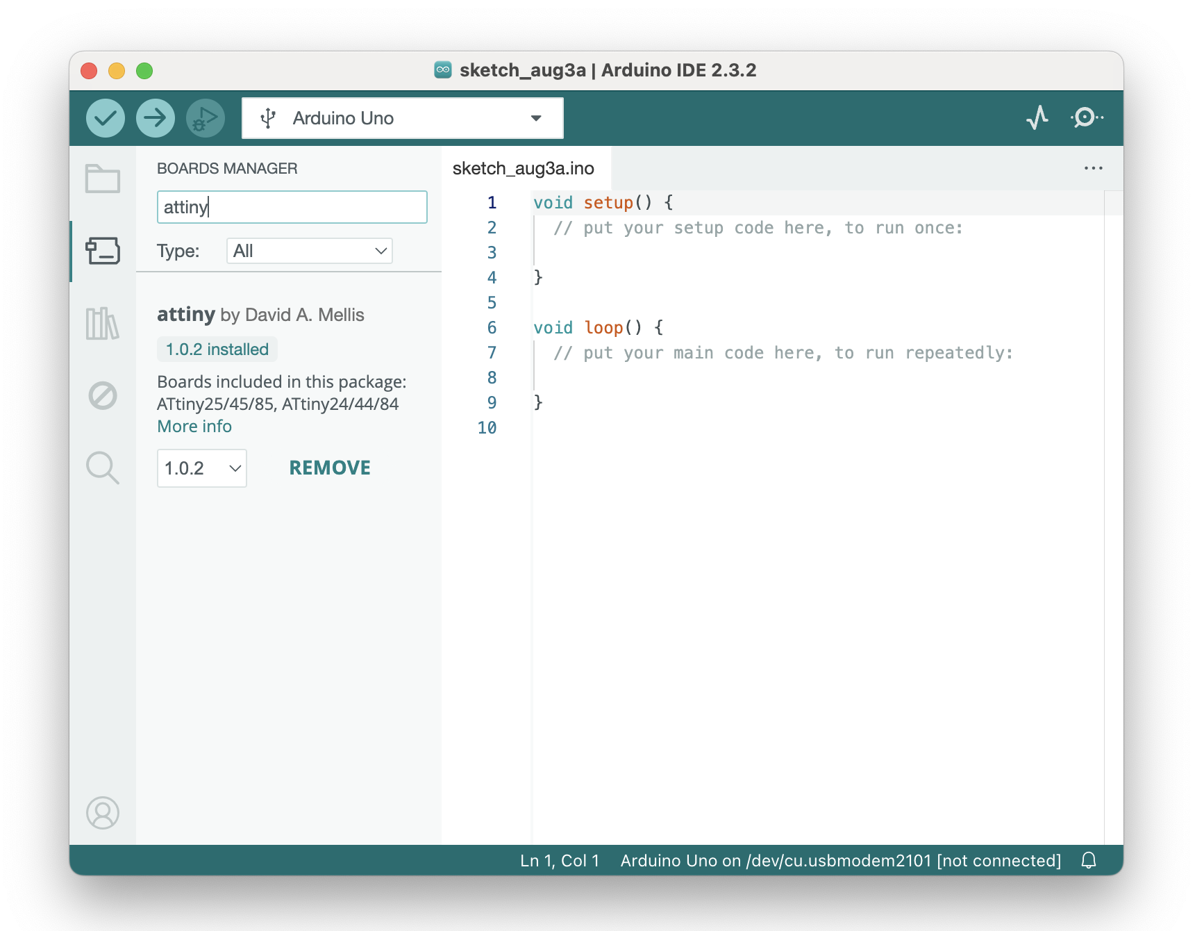
- Open the Boards Manager:
- Go to Tools > Board > Boards Manager.
- Search for "attiny" and install the "Attiny by David A. Mellis".
Select the ATtiny85 board:
- Go to Tools > Board and select ATtiny25/45/85.
Select the ATtiny85 processor:
- Go to Tools > Processor and select ATtiny85.
Select the clock speed:
- Go to Tools > Clock and select Internal 8 MHz.
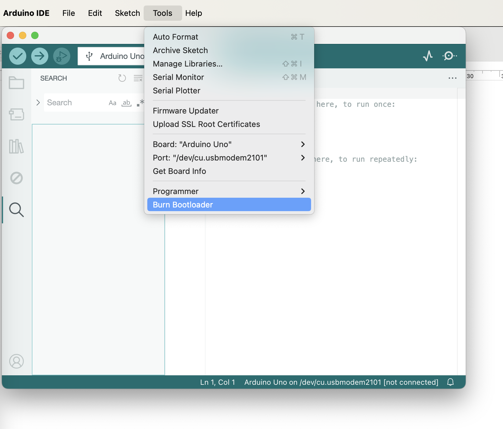
Step 4: Burn the Bootloader
Burn the bootloader to configure the ATtiny85 fuses:
- Go to Tools > Programmer and select Arduino as ISP.
- Go to Tools > Burn Bootloader.
During the bootloader burning process, you will observe flashing LEDs on the Arduino Uno. This process will take a few seconds. Once the bootloader has been successfully burned, the LEDs on the Arduino Uno will stop flashing, and a confirmation message will appear in the Arduino IDE.
Step 5: Upload Your Sketch to the ATtiny85
- Write your sketch as you would for any other Arduino board.
- Select the correct programmer:
- Go to Tools > Programmer and make sure Arduino as ISP is selected.
- Upload your sketch: Use the Upload Using Programmer option by going to Sketch > Upload Using Programmer.
Example Blink Sketch
To operate the ATtiny85, connect VCC and GND as the minimum requirements. For a basic LED blink program, use digital pin 0 to control the LED, and include a 47-ohm resistor in series with the LED to limit the current at 3V. The operating voltage range for the ATtiny85 is 2.7V to 5.5V.

The following code snippet demonstrates a basic LED blinking program for the ATtiny85. Upload the
void setup() {
  pinMode(0, OUTPUT); // Use pin 0 (physical pin 5 on ATtiny85)
}

void loop() {
  digitalWrite(0, HIGH); // Turn the LED on
  delay(1000); // Wait for a second
  digitalWrite(0, LOW); // Turn the LED off
  delay(1000); // Wait for a second
}